View Series And Parallel Circuits Diagrams Images. In this circuit, we have two loops for the current to flow through: Simple circuits (ones with only a few components) are usually fairly straightforward for beginners to understand.
Lessons In Electric Circuits -- Volume I (DC) - Chapter 5 from www.ibiblio.org In series circuits, current is constant throughout the loop so that you can measure a single component's current in a series circuit to determine the current of all the circuit's elements. Series circuits are useful if you want a warning that one of the components in the circuit has failed. Andersen contrasts series and parallel electrical circuits.
Mechanical engineers require some basic knowledge of circuitry, electricity and related this instructable will help one solve and learn one of the foundations of electrical circuits.
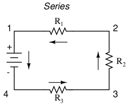
In a series circuit, the multiple components are connected in a cascaded manner i.e., the tail of a component is connected to the head of the other. Looking at the schematic diagram, we see that points 1, 2, 3, and 4 are all electrically common. Andersen contrasts series and parallel electrical circuits. Draw a new circuit diagram with the newly reduced equivalent resistor.
Share this post
0 Response to "Series And Parallel Circuits Diagrams"

0 Response to "Series And Parallel Circuits Diagrams"
Post a Comment